Original Prusa MINI+
As highlighted in my previous article, over the past week I have been building the Original Prusa Mini+ kit.
The “kit” version is shipped as individual parts, requiring manual assembly. The Prusa documentation estimates a 5 to 8 hour build time for one person, with 194 steps.
Thankfully, the assembly instructions (linked below) are exceptional and the package includes all the required tools (e.g. Allen keys, TORX key, pliers, wrench, etc.)
This article highlights my build process, with a few photos and commentary.
I started with the Y Carriage assembly (image below), which secures and manoeuvres the heatbed.
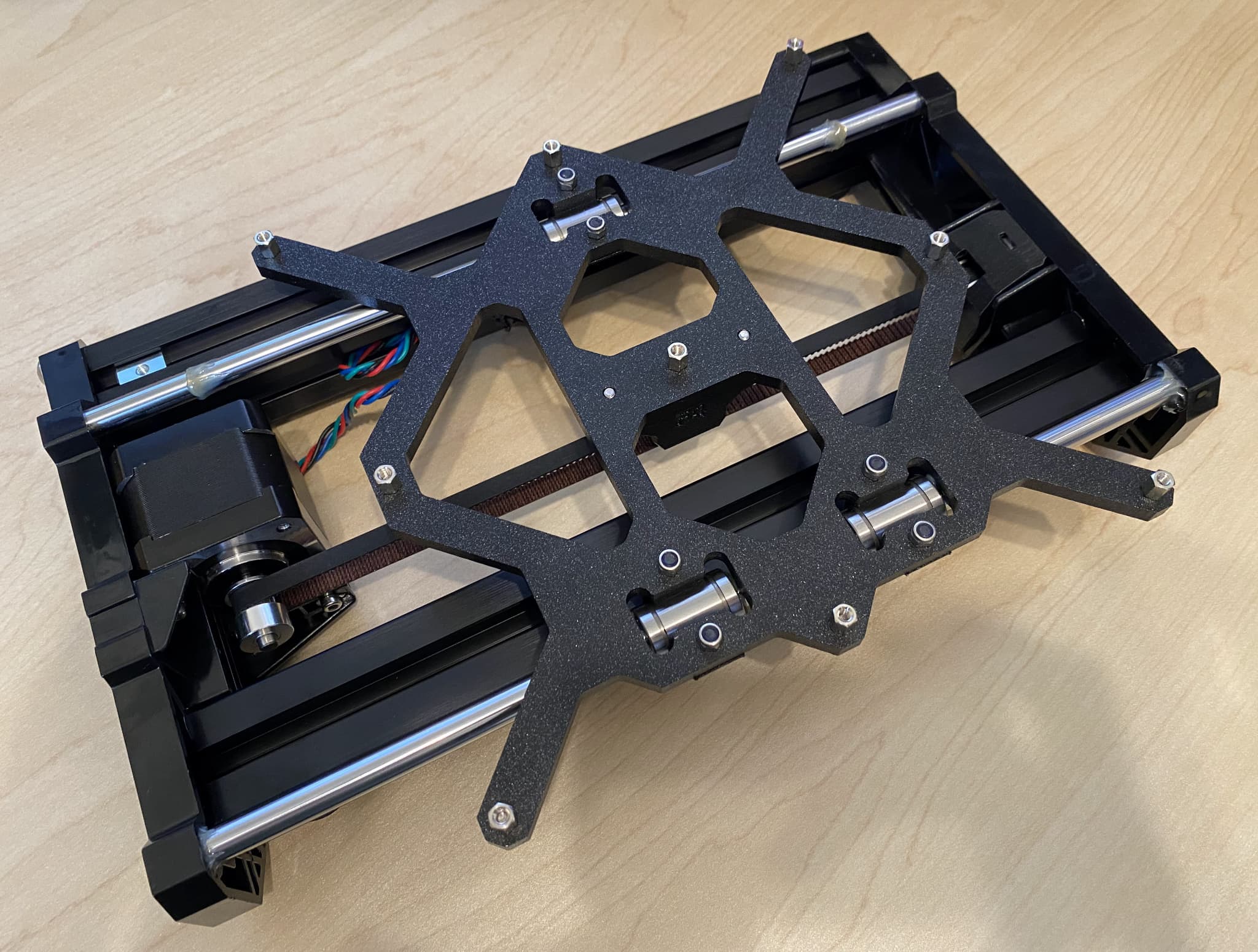
I had expected the Y-motor and Y-axis belt installation to present a challenge, but thankfully the MINI-Y-belt-holder includes the required grooves to secure the belt teeth (no fiddly screws required). Additionally, the tension of the belt can be easily manipulated via the MINI-Y-plate-front (a nice design touch).
I did not enjoy the bearing lubrication process, which reminded me of applying thermal paste, where the quantity can impact performance.
Once complete, I started on the Z-axis assembly (image below), which includes the buddy board enclosure and PCB itself. The buddy board enclosure is used to secure the Z-axis to the previously assembled Y Carriage. The 32-bit PCB is custom-built by Prusa, approximately the same size as a Raspberry Pi 4.
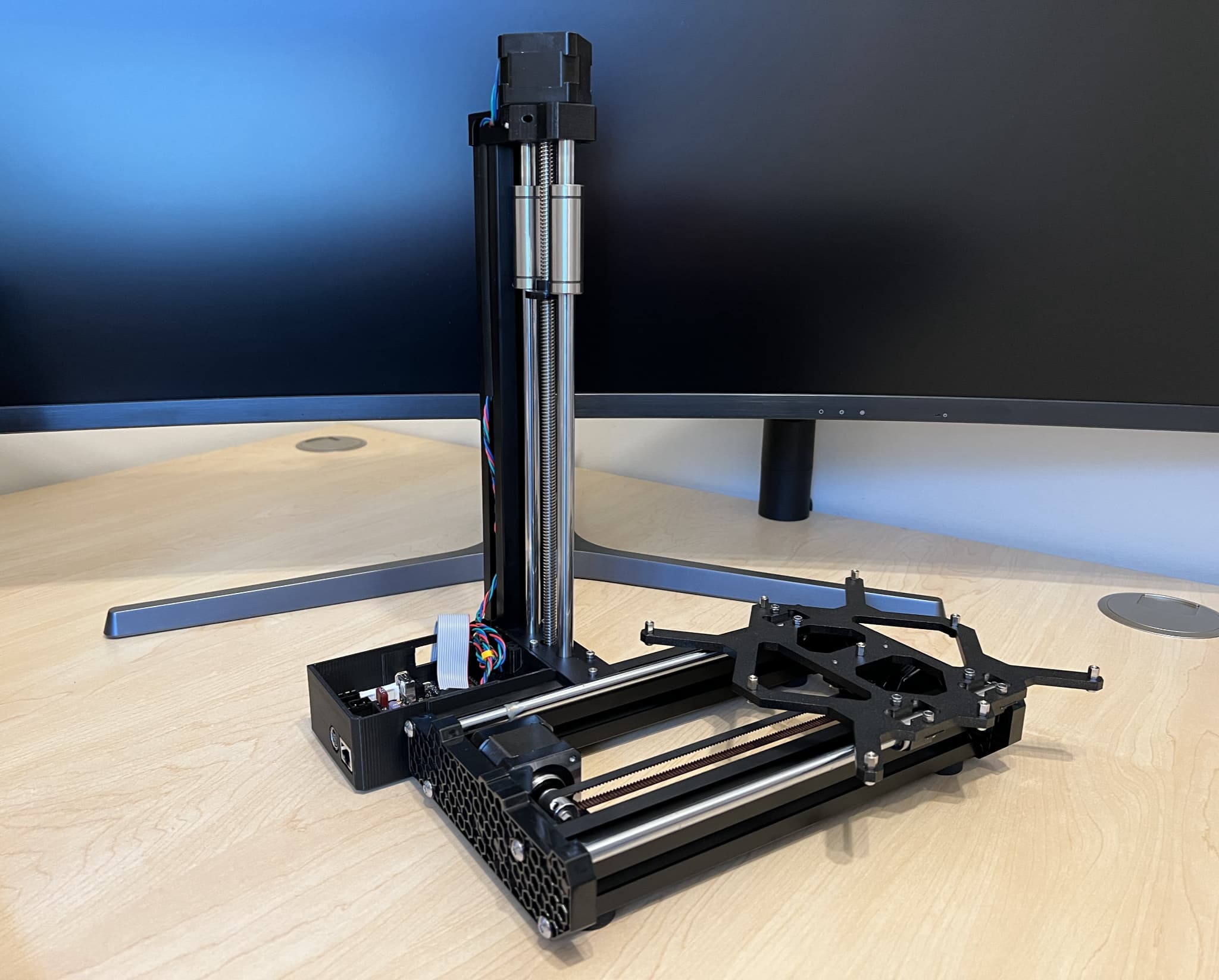
Thanks to the larger components, the Z-axis assembly was relatively straightforward. However, I did need to apply a disconcerting amount of force to ensure the steel rods were fully seated. This is a testament to the 3D printer parts, which feel reassuringly dense.
In my opinion, the next phase was the most complex, covering the X-axis, extruder and print head (image below).
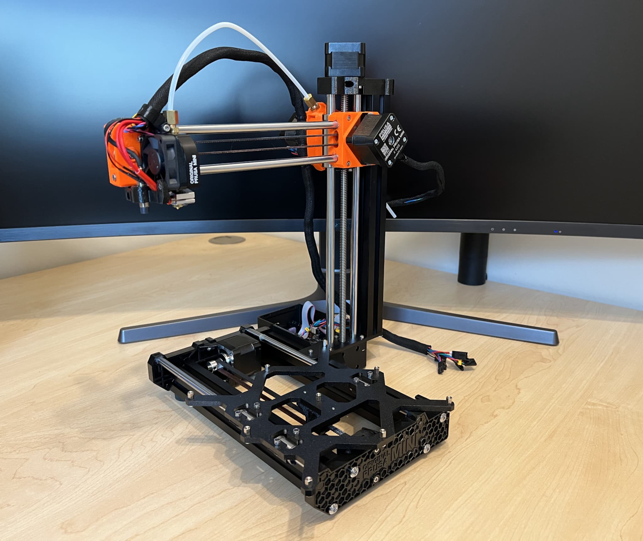
With many small and moving parts, I found myself double-checking my work to ensure the instructions had been followed correctly. The printhead is “where the magic happens”, including the hotend, which can reach temperatures of 280C. The installation of the PTFE tube and SuperPINDA sensor requires accuracy, therefore I would recommend allocating additional time for this section.
My build also included the optional filament sensor (£23), which detects the presence and movement of filament, which adds convenience and helps protect against spoiled builds.
Finally, I installed the Heatbed and LCD (image below). The heatbed has a larger surface area and can reach temperatures of 100C, therefore care should be taken when connecting the cables and attaching the cable cover.
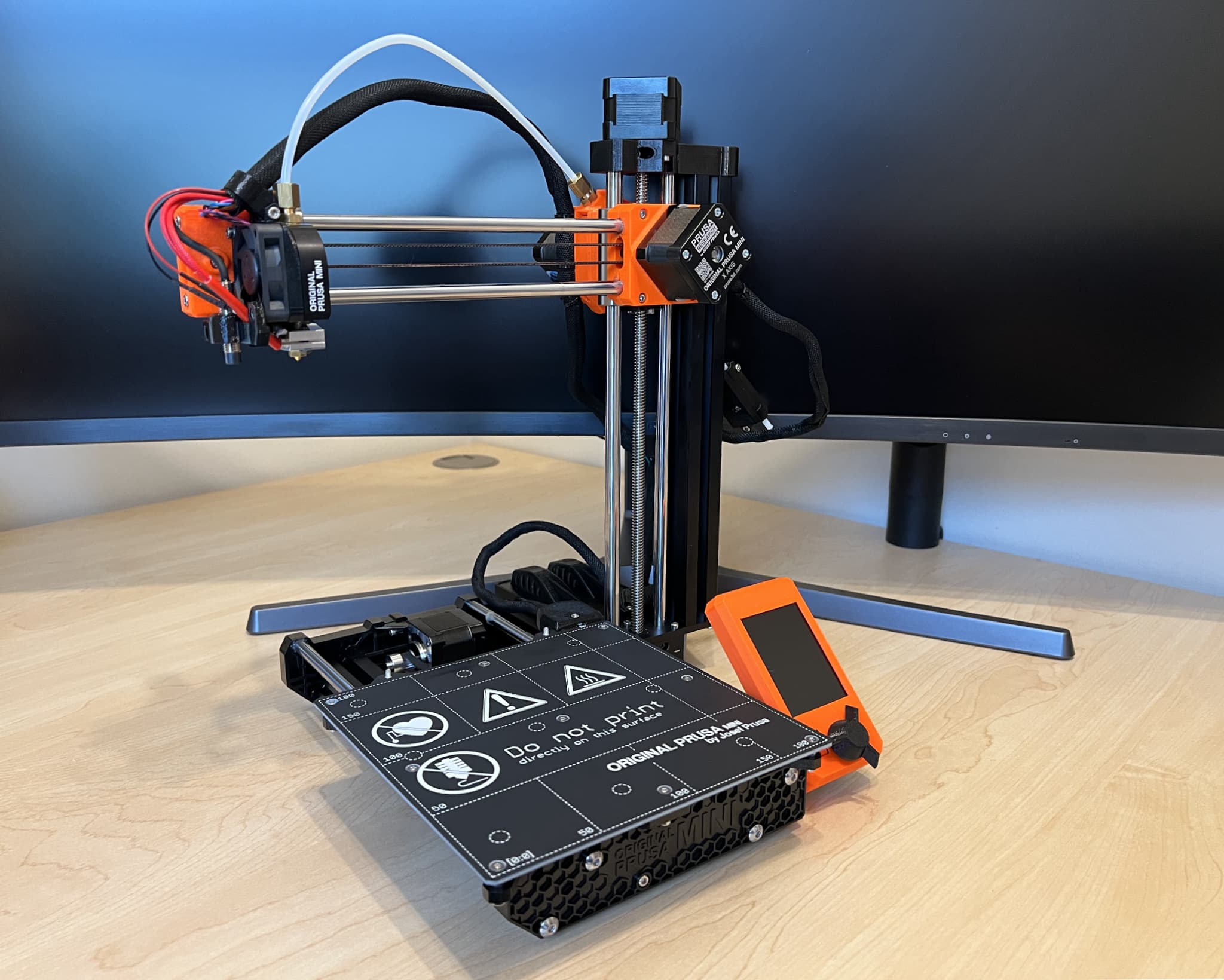
The LCD comes pre-assembled, therefore simply needs to be mounted (one screw) and connected to the PCD via a ribbon cable.
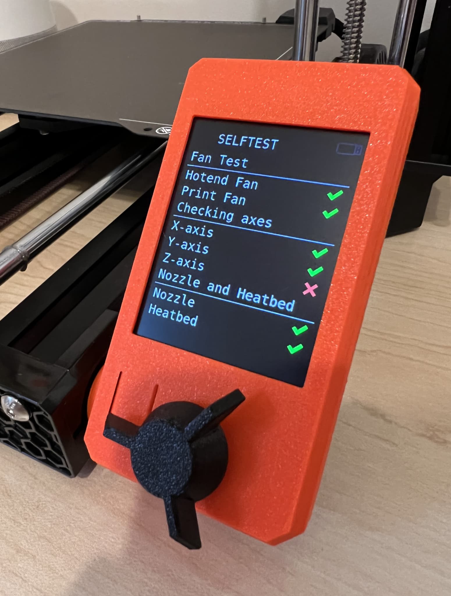
With the assembly complete, I powered on the printer and completed the initial setup, which includes a self-test and automatic calibration. Unfortunately, the self-test failed due to an issue with the Z-axis (image below).
After some troubleshooting (Google and Reddit), I identified the issue. I had over-tightened the trapezoidal nut (image below), which restricted the movement of the Z-axis motor.
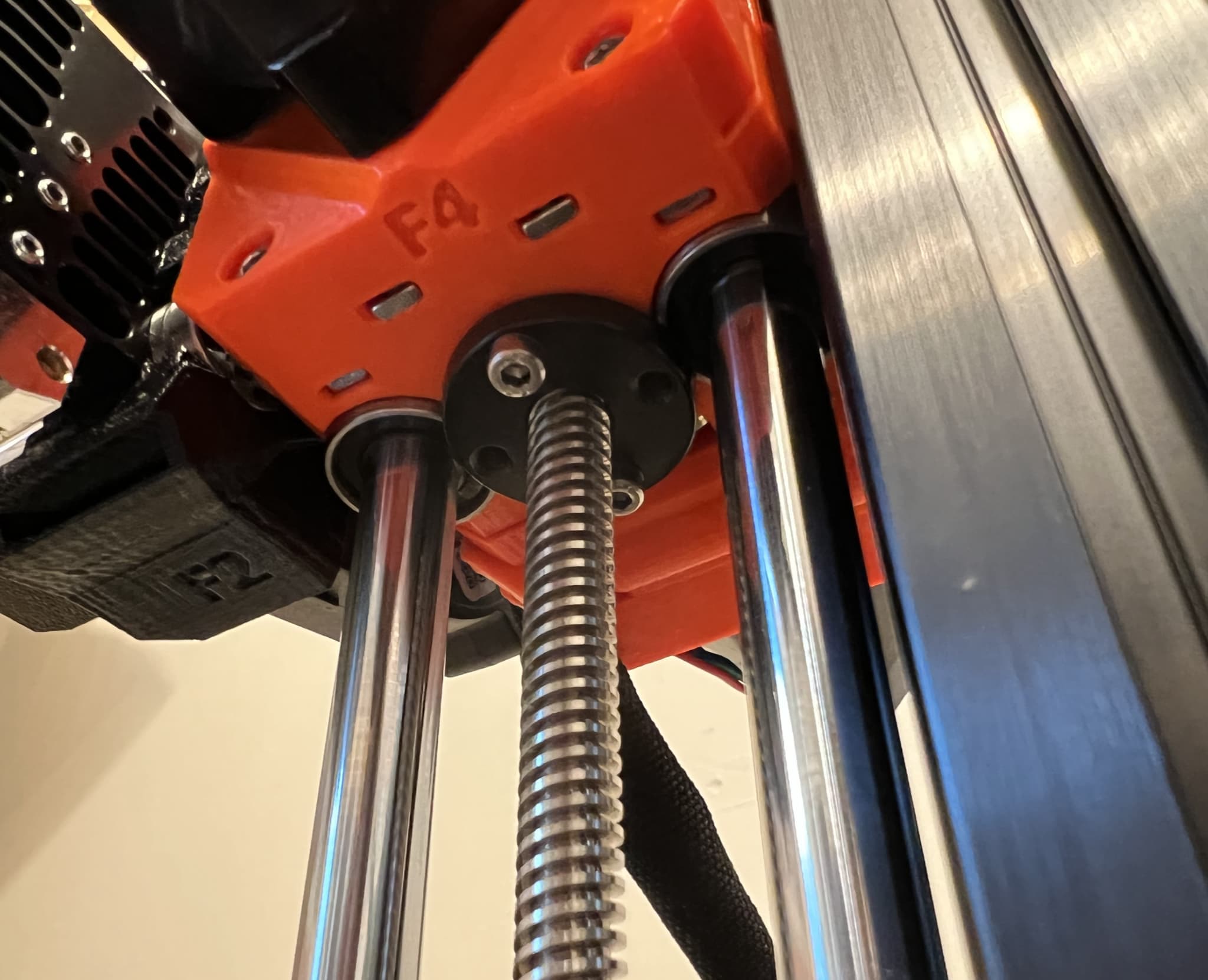
With the two screw tension reduced, the Z-axis motor kicked into action and the self-test passed successfully!
That’s it! The build took me approximately six hours, split over several days. It is worth re-emphasising the quality of the assembly instructions, which are among the best I have ever used. Therefore, if you are in the market for a Prusa 3D printer, I would have no hesitation in recommending the “kit” version.
Over the next week, I plan to test the printer, starting with some simple print jobs. Stay tuned for the results.